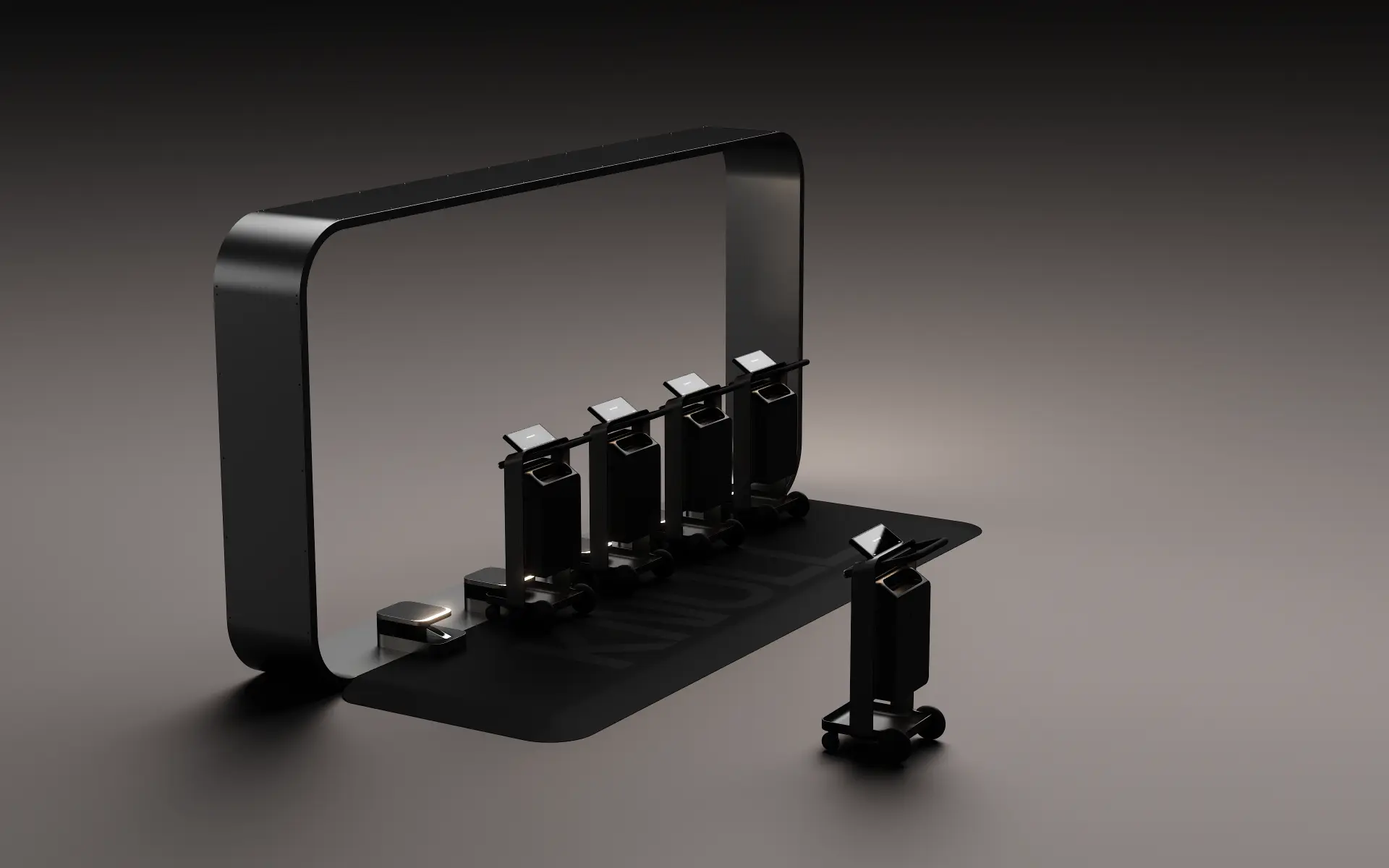
Knull Dock
The physical anchor of the Knull network.
A trolley is a product. A dock makes it infrastructure. Knull Docks are the physical anchor of the Knull network: they retain and release units, identify each one, reconcile it to its session, show per-bay status and report dock and fleet state to the platform.
01What a dock does
Six responsibilities in one fixed point.
Retention
Units are held securely between sessions. Custody is a dock state, not an assumption.
Release
A unit is released only to a verified session, and only if it reports itself fit for use.
Power interface
A charging/power interface is included where the final engineered configuration requires it.
Identity & access
The dock verifies the access credential and binds the unit to a session.
Connectivity & telemetry
Dock and fleet state are reported to the Knull Platform for operational visibility.
Status & interface
Clear status at the bay tells visitors and staff what is available, at a glance.

02Architecture
Modular bays. Distributed network. Placed by demand.
Docks use a multi-bay, modular architecture. Placement and capacity are determined by destination layout, demand, entrances and exits, parking interfaces and operational requirements — and multiple docks operate together as a distributed network.
Bay architecture
Repeatable bays combine into clusters; cluster size follows the demand of the zone rather than a fixed product size.
Edge logic
Custody and core release decisions are made at the dock, so a network interruption does not strand visitors.
Service access
Serviceability is a design requirement; the service approach is confirmed through prototype and engineering validation.
Installation
Site requirements — position, power and connectivity — are established during site assessment for each destination.
03In the network
From one dock to a destination-wide network.
- 01
Dock
One cluster serves one zone: an entrance, an atrium, a car park lobby.
- 02
Cluster pattern
Clusters are placed where journeys begin and end, across levels and entrances.
- 03
Network
The platform sees every cluster at once, so availability can be balanced across the destination.
- 04
Estate
The same dock standard repeats across destinations, so operations stay consistent.
Specifications
Bay count, dimensions, charging method, electrical requirements, ingress protection, interface and connectivity specifications are subject to engineering validation and are shared during site assessment rather than published here.
Next step
Plan where docks would sit in your destination.
Start with an indicative assessment: your layout, entrances and levels, and where journeys begin.